Industry News
Home / News / Industry News / How Do Miniature Bearings Power Precision Engineering and High-Speed Machinery

How Do Miniature Bearings Power Precision Engineering and High-Speed Machinery

Fundamental Definitions and Classifications of Miniature Transmission Systems

In modern precision mechanical design, miniaturization has become the core driver of technological progress. From lightweight drone motors to precision handheld medical devices, miniature transmission systems play a role akin to "nerve endings" in critical functions. To understand this field, it is first necessary to define the boundaries between miniature bearings and micro bearings.

Typically, we classify bearings with an outer diameter of less than 9mm and an inner diameter of 1mm to 3mm as miniature bearings, while products with even smaller outer diameters or those used in extremely compact spaces are termed "micro bearings." Although these components are tiny, they must withstand complex dynamic loads while ensuring extremely high rotational precision.

The evolution of mini bearings reflects the human pursuit of space efficiency and energy optimization. In early precision watch mechanisms, miniature bearings achieved a qualitative shift in reducing frictional loss by minimizing physical contact areas. Today, in high-speed cooling fans or miniature gyroscopes, they ensure precise equipment control through high operational stability.

For engineers, understanding industry standards for miniature bearings is vital. Currently, mainstream international size grading is based on ISO and ABEC standards, which specify not only inner diameter, outer diameter, and width values but also define rotational tolerances. Standardization not only reduces the difficulty of design and replacement but also makes global precision collaboration possible.

To intuitively display the classification differences of these miniature components, the following table outlines their main technical parameter characteristics:

Bearing Type Typical Size Characteristics (Outer Diameter) Core Application Fields Load Characteristics
Standard Miniature Bearings 5mm - 9mm Household motors, fitness equipment Primarily radial load
Ultra-miniature Bearings 2mm - 4mm Electronic equipment, precision instruments Light load, high speed
Precision-grade Bearings 3mm - 9mm Medical devices, model aviation High rotational precision, low noise

During the initial design phase, deviating from these standard sizes not only increases the cycle and cost of custom development but can also lead to premature bearing failure due to unreasonable lubrication channel design. Therefore, becoming familiar with these classifications is not just a technical requirement, but the first step in ensuring the long-term operation of miniature systems.

In-depth Analysis: Ball Bearings and Geometric Diversity

At the heart of miniature transmission systems, miniature ball bearings occupy an absolute market position due to their unique rolling structure. The core logic of ball bearings lies in achieving rolling friction through point contact, thereby greatly reducing mechanical energy loss.

In deep groove structures, the raceway is machined into an arc slightly larger than the radius of the rolling ball. This design allows the bearing to withstand radial loads while also handling bidirectional axial loads to a certain extent. This is why it is so widely applied across various miniature rotating parts—it is sufficiently "versatile."

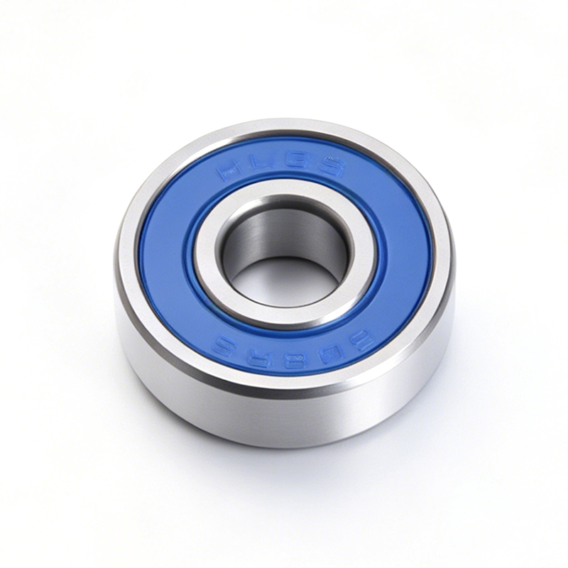
However, based on differences in application scenarios, we have derived distinctions between micro ball bearings and mini ball bearings. The former focuses more on weight reduction in extreme spaces and is often used for supporting precision encoders or sensors, where requirements for starting friction torque are extremely high. The latter is used more for handling mechanical vibrations and is often found in remote-controlled models or small drive devices, where structural strength and sealing levels are prioritized.

In cross-border engineering collaboration, the global interoperability of metric miniature bearings is extremely high. Compared to non-metric series, metric designs often have superior tolerance adaptability when matching shaft diameters. The following table compares the operational characteristics of metric miniature bearings across different precision grades:

Precision Grade (ABEC/ISO) Typical Radial Runout Limit Recommended Application Scenarios Lubrication Friction Characteristics
P0 (General Grade) Relatively high General industrial use, DIY models Stable friction coefficient
P5 (Precision Grade) Stringent High-speed fans, high-speed motors Minimal frictional heat
P4 (Ultra-precision Grade) Ultimate Medical scanning equipment, lab turntables Extremely low friction, minimal thermal expansion impact

This classification system based on metric standards allows designers to achieve iterative performance upgrades in tiny spaces simply by changing the precision grade rather than the structure. Whether pursuing the ultimate rotational speed for a motor or requiring stringent noise levels for household precision equipment, metric miniature bearings provide the broadest engineering "language."

Special Design Bearings: Addressing Complex Motion Requirements

When a single radial support cannot meet complex dynamic environments, engineers must turn to bearing structures designed for specific mechanical properties. The "special designs" of miniature bearings are not merely changes in geometric shape, but are intended to distribute loads, limit displacement, or simplify assembly processes in tiny spaces.

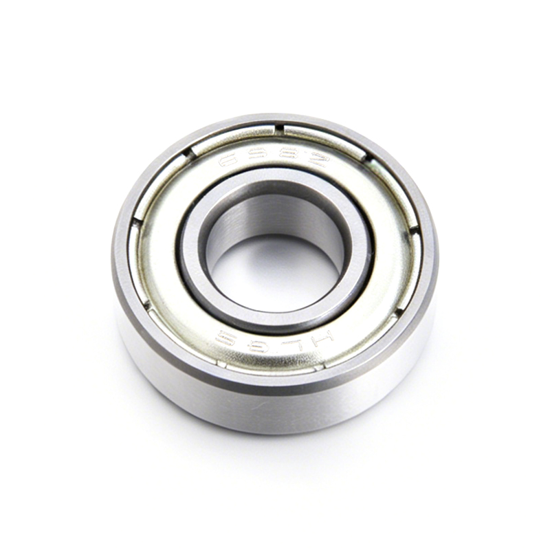
Miniature deep groove ball bearings remain the cornerstone of this field. Their raceway curvature radius is slightly larger than the steel ball radius, allowing the bearing to be in an ideal contact state when subjected to pure radial force. This design is highly suitable for high-speed rotation, and because its friction torque is small, it is often used in precision micromotors sensitive to energy efficiency.

When facing situations requiring precise positioning and the presence of axial loads, miniature angular contact bearings demonstrate their advantages. Unlike deep groove ball bearings, their inner and outer ring raceways have relative displacement, specifically designed to withstand unidirectional axial loads or combined loads. These bearings are usually used in pairs, applying preload to eliminate axial clearance and enhance the rigidity of the entire rotating system.

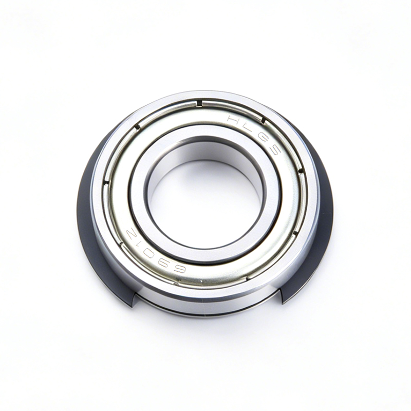
For forces perpendicular to the axis, miniature thrust bearings provide dedicated axial support. They function like a tiny "load-bearing gasket," effectively handling pressure from the shaft end. In addition, miniature flanged bearings are highly valuable in assembly. Their outer ring edge has a protruding flange, allowing the bearing to be positioned directly against the surface of a hole. This eliminates the need to machine complex notches in the housing, greatly simplifying the structural design of small equipment and ensuring axial stability.

To assist in engineering decisions, the following table compares the load-handling capabilities of these special designs:

Bearing Structure Type Radial Load Capacity Axial Load Capacity Ease of Installation Core Engineering Advantage
Deep Groove Ball Bearings Excellent Fair High Versatile, adapts to high speeds
Angular Contact Bearings Moderate High Moderate High rigidity, resists axial movement
Miniature Thrust Bearings Very Low Ultimate Low Dedicated to continuous axial pressure
Flanged Bearings Excellent Fair Very High Simplifies housing positioning, resists lateral shift

When selecting these special bearings, the overall motion trajectory of the system must be considered. For instance, if equipment frequently experiences axial vibration during operation, choosing angular contact bearings or flanged deep groove ball bearings often significantly improves the overall lifespan and reliability more than simply pursuing a higher precision standard. Combining these structures reasonably is the key to achieving efficient rotation in miniature systems.

The Application of Roller Technology in Miniature Fields

While ball bearings dominate in miniature applications, tiny roller bearings are often the top choice for engineers when dealing with higher loads or extreme requirements for space rigidity. Unlike the point contact of ball bearings, roller bearings distribute loads over a wider area via line contact. This geometric advantage allows them to carry larger loads within smaller sizes.

Miniature roller bearings usually come in forms such as cylindrical rollers, needle rollers, and tapered rollers. In extremely restricted spaces, such as in the output shafts of miniature gearboxes or small actuators, needle roller bearings become the prime choice for saving space in high-load environments due to their extremely thin cross-sectional height.

However, the design of miniature roller bearings also faces unavoidable engineering constraints. Due to the line contact characteristic, stress concentration easily occurs at the ends of the rollers. Furthermore, during high-speed rotation, the relative sliding velocity between the rollers and the raceway is much higher than in ball bearings, leading to increased frictional heat, which imposes near-demanding requirements on the integrity of the lubricating oil film.

To ensure the stable operation of miniature rollers at high speeds, structural optimization of the cage is the core of the design. The cage not only secures the position of the rollers but also guides lubricant within the tiny gaps, reducing "skewing" wear caused by rolling element tilting. The following is a performance comparison between roller bearings and ball bearings in miniature application environments:

Performance Dimension Miniature Roller Bearings Miniature Ball Bearings
Radial Load Capacity High (Line contact) Moderate (Point contact)
Limiting Speed Lower (Higher frictional heat) Extremely High (Lower frictional heat)
Space Usage (Cross-section) Extremely Low (Needle type) Moderate
Axial Load Capacity Almost zero (unless special structure) Moderate
Sensitivity to Misalignment High Lower

Engineering Best Practices: When selecting roller technology, the operating conditions of the equipment must be carefully evaluated. If the system needs to cope with high-frequency, intense radial impacts and the speed is within a controllable range, the durability of miniature roller bearings far exceeds that of ball bearings. Conversely, for precision motors pursuing low starting torque and high stability, avoid roller structures and use deep groove ball bearings. For miniature roller bearings, the choice of oil film determines the upper limit of their lifespan; it is recommended to introduce forced lubrication or highly targeted grease filling solutions during the design stage to handle the high local pressure brought by line contact.

Precision Manufacturing and High-Performance Material Selection

In the field of miniature transmission, the performance ceiling of a bearing is often determined by the combination of materials science and manufacturing processes. As applications expand into extreme environments (such as vacuum, ultra-low temperatures, and corrosive conditions), miniature ceramic bearings are increasingly entering the mainstream. Silicon nitride (Si3N4) as a core material has a density only 40% that of steel, meaning it significantly reduces centrifugal force during high-speed operation, thereby dramatically increasing the bearing's speed limit. Furthermore, the inherent electrical insulation of ceramic material effectively avoids electrical erosion problems in miniature motors.

However, the key to determining final product quality lies in the manufacturing tolerance control of precision miniature bearings. In the micrometer world, the roundness of the inner and outer rings, the surface roughness of the raceway, and the dimensional consistency of the rolling elements directly determine the noise level and lifespan of the equipment.

The machining process for micro miniature bearings is extremely complex. It involves not only micro-machining, turning, and grinding but also a series of special control processes such as ultrasonic cleaning and clean-room assembly. Any microscopic dust or metal debris inside the bearing can become a "trigger" for failure. Therefore, the quality control system for miniature precision bearings typically includes fully automated laser inspection and vibration acceleration measurement to eliminate even the slightest processing flaws.

To better understand the contribution of different materials and manufacturing grades to performance, the following table compares material properties and the influence of precision on bearing performance:

Key Parameters Chrome Steel (Standard) Full Ceramic (Silicon Nitride) Hybrid Ceramic (Steel Ring + Ceramic Ball)
Density High Low (Lightweight) Moderate
Thermal Expansion High Low (Resists deformation) Moderate
Electrical Insulation None Excellent Good
Lubrication Dependency High Low (Can run dry) Moderate
Typical Environment General Industry Aerospace/Extreme Environments High-speed Motors/High-performance Rotors

In practical selection, one cannot simply assume that ceramic material is the "master key." While ceramic bearings hold an absolute advantage in speed and chemical resistance, precision steel bearings perform better in toughness and impact resistance. If your application environment involves frequent start-stop impacts, even in high-performance scenarios, a hybrid ceramic structure is often the best balance between cost and lifespan.

Additionally, manufacturing precision grades (e.g., ABEC 5 vs. ABEC 7) have significant performance differences in miniature applications. ABEC 5 grade bearings are suitable for the vast majority of precision speed control scenarios, while ABEC 7 or higher grade bearings mean smaller vibration amplitudes and higher rotational consistency, which is critical in precision optical instruments or high-frequency vibration sensing equipment. Choosing the right grade of bearing is essentially "customizing" the performance boundary for the equipment's operating environment.

Best Practices for Installation, Lubrication, and Troubleshooting

Even with top-tier precision bearings, performance will be severely compromised if installation and maintenance methods are improper. In the field of miniature transmission, "precision" is not only reflected in manufacturing but also in the respect for the installation environment.

Cleanliness is a Lifeline: The clearance of miniature bearings is often only a few micrometers. If dust or metal particles invisible to the naked eye exist at the installation site, they will directly embed into the raceway, leading to premature wear. Operations must be carried out in a dry, clean, controlled environment (such as a clean workbench). Do not remove the bearing's sealed packaging prematurely to prevent contaminants from entering.

Key Installation Methods: Directly striking the end face of the bearing inner or outer ring is strictly prohibited, as this will cause dents in the raceway from the rolling elements. A dedicated sleeve should be used to ensure uniform force on the face of the ring being interference-fitted. If conditions permit, a heat-fitting method can be used (slightly heating the bearing to about 80°C so it expands for easy installation onto the shaft). However, with miniature bearings, the heating time must be strictly controlled to prevent altering the material's heat treatment state or damaging the plastic cage.

The "Golden Balance" of Lubrication: Excessive grease filling is one of the most common causes of miniature bearing damage. In high-speed environments, too much grease creates intense stirring friction, leading to abnormal temperature rises and lubricant deterioration. Generally, the fill amount in a miniature bearing should be controlled to between one-third and one-half of the internal space.

Comparison of lubrication strategies for different application scenarios:

Lubrication Type Applicable Conditions Advantages Limitations
Light Mineral Oil Very high speed, light load Extremely low resistance, good heat dissipation Short duration, easy to leak
Synthetic High-Temp Grease Med-high speed, long duration Strong adhesion, long life Higher starting resistance
Solid Lubrication (MoS2) Vacuum, extreme temp swings No evaporation, non-contaminating Limited life, lower load capacity

A Quick Guide to Troubleshooting: If abnormalities occur during bearing operation, the cause of failure can be initially judged through the following characteristics:

Increased Noise: Usually caused by lubrication failure or flaking due to tiny foreign particles in the raceway. Check if the seal is loose.

High Temperature: Primarily check for excessive grease filling or an overly tight installation fit (clearance completely eliminated).

Rough Rotation: Check for fretting wear or if the housing hole caused inner ring deformation due to machining errors.

Remember, failures in miniature bearings are often not due to the quality of the bearing itself, but because the tolerances of the mating parts (shaft or housing) were not designed properly. Regularly monitoring temperature rise and vibration frequency can often reveal problems before the bearing fails completely.

Frequently Asked Questions (FAQ)

Q1: How to distinguish between deep groove and angular contact structures in miniature bearings?

Visually, the inner and outer ring shoulders of a deep groove ball bearing are symmetrical and can handle bidirectional axial loads. In contrast, the shoulders of an angular contact bearing are typically asymmetrical (one high, one low), which dictates that it can only withstand unidirectional axial loads. If you select the wrong orientation in a device, the bearing will fail quickly as the load point exceeds the raceway.

Q2: Are ceramic materials always better than steel when choosing miniature bearings?

Not necessarily. While silicon nitride balls possess excellent wear resistance and speed limits, the hardness difference between ceramic balls and metal raceways can cause plastic deformation of the raceway under intense impact. If you are pursuing high speed and insulation, choose ceramic; if you are looking for cost-effectiveness and impact resistance, high-quality chrome steel remains the industry mainstream.

Q3: Why does my miniature equipment produce noise soon after running?

In the vast majority of cases, it is a lubrication issue or contamination. It is recommended to check whether the seal ring was crushed during installation. Additionally, if the fit tolerance between the shaft and the bearing inner bore is too tight, the original tiny clearance will be "crushed," forcing the balls to slide rather than roll, resulting in a whistling sound.

Q4: Can metric and imperial miniature bearings be interchanged?

No. The size systems for metric (e.g., ISO standard) and imperial (e.g., R-series bearings) are completely different. Even if the values look similar, their combinations of inner diameter, outer diameter, and width often differ. Forced interchange will lead to loose fits or inability to assemble. Design benchmarks must be determined.

Q5: What are the special precautions for installing flanged bearings?

The flange is a positioning surface; ensure it fits perfectly against the housing end face during installation. If the flange face is subjected to uneven force due to tilting during press-fitting, it is very easy to cause breakage at the connection between the flange and the outer ring. Using a flat-faced press tool can effectively reduce such risks.

Q6: How should the preload of miniature bearings be controlled?

In systems requiring high rotational precision, preload is necessary, usually achieved through wave spring washers or adjustment shims. If the preload is too high, frictional heat increases; if too low, system vibration cannot be suppressed. It is recommended to account for the thermal expansion coefficient of the device during operation and leave a tiny margin of clearance.

Recent Articles