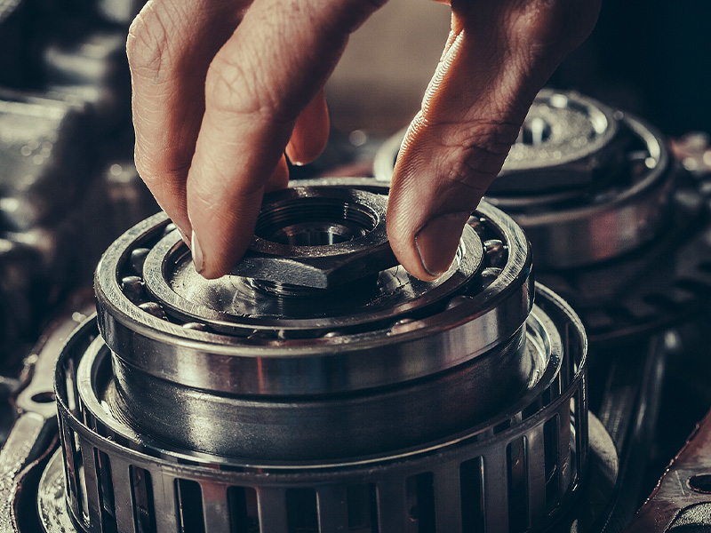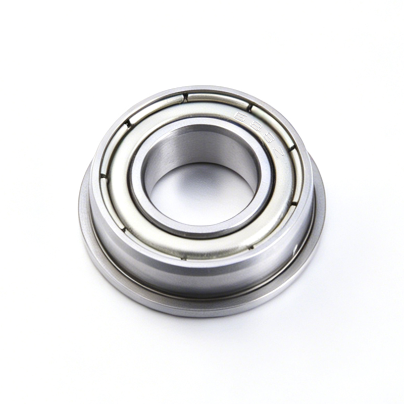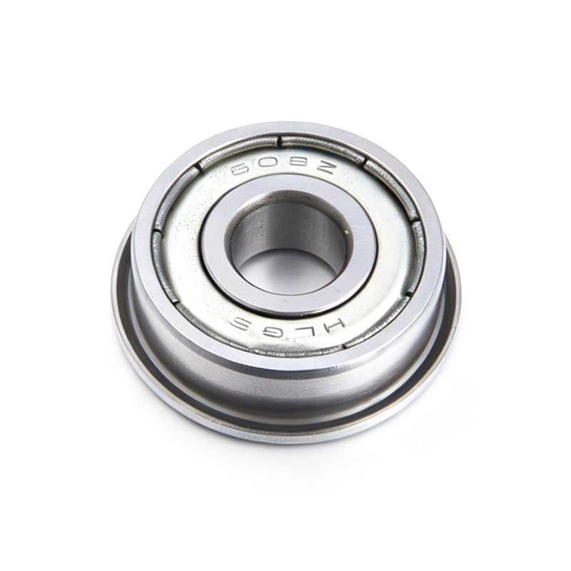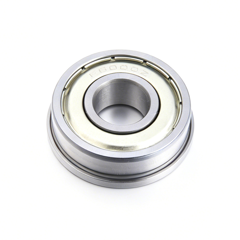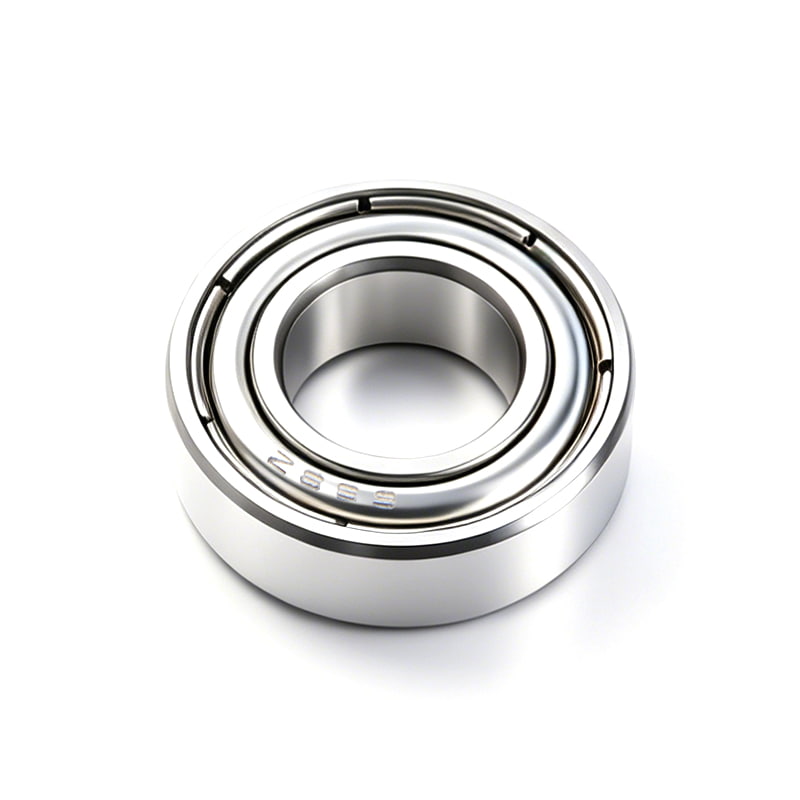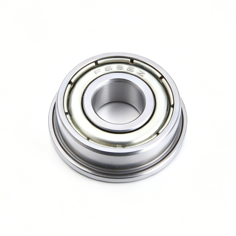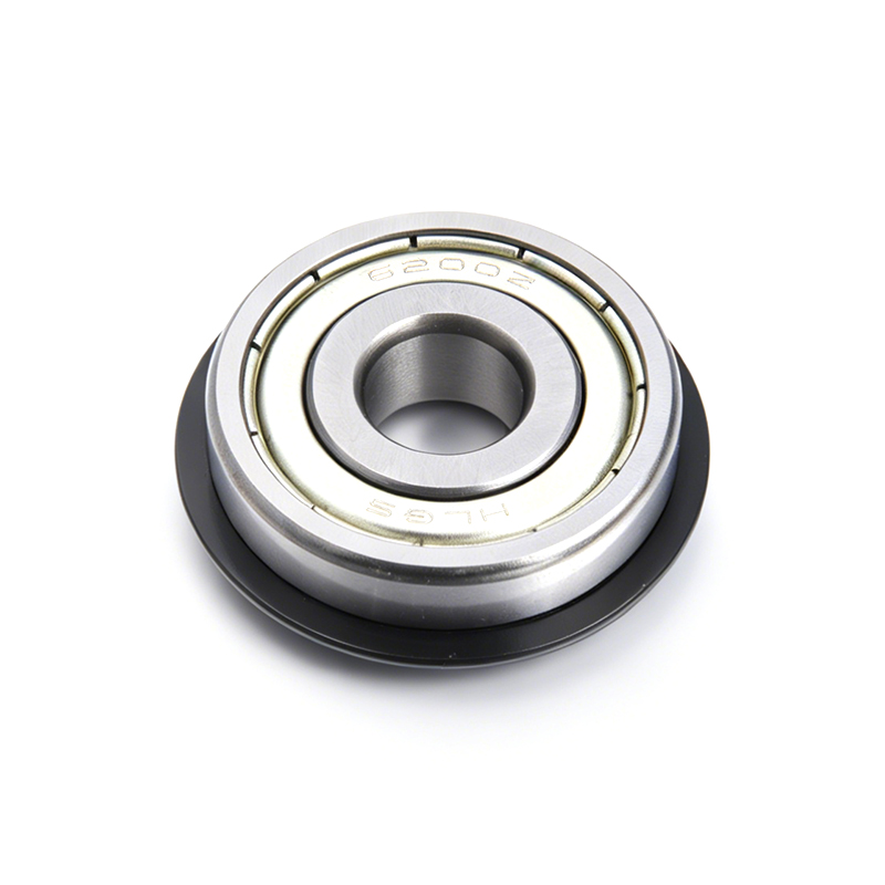
A flanged bearing is a standard ball or roller bearing with an integrated collar (the flange) extending from the outer ring. The flange's primary job is to locate the bearing axially within a housing bore, preventing it from sliding through or shifting along the shaft during operation — a problem that standard bearings without a flange must otherwise solve using retaining rings, shoulder steps machined into the housing, or spacers and locknuts.
In practical terms, this means flanged bearings reduce the number of components needed in an assembly, simplify machining requirements for the housing, and make alignment more repeatable across production runs. In applications like conveyor rollers, printer mechanisms, and small motor housings, switching from a standard bearing plus a retaining assembly to a single flanged bearing can reduce the part count in that section of the assembly by 2–4 components. The rest of this article breaks down exactly which problems flange design addresses, where it falls short, and how to decide between flanged and standard bearings for a specific application.
The most immediate problem flange design solves is keeping the bearing in a fixed axial position relative to the housing, without relying on separate retaining components.
With a standard (non-flanged) bearing, the outer ring is a plain cylinder, meaning nothing inherently stops it from sliding along the bore axis under vibration or thrust load. Designers typically address this with a machined shoulder in the housing on one side and a retaining ring, snap ring, or end cap on the other. Each of these solutions requires additional machining precision and assembly steps.
A flanged bearing's collar sits flush against the face of the housing bore, acting as its own stop. This means the housing only needs a straight, unshouldered bore rather than a stepped one — a meaningfully simpler and cheaper machining operation, particularly in thin-walled housings like sheet metal brackets or injection-molded plastic components, where machining a precise internal shoulder is difficult or impossible.
Standard bearings rely on a certain amount of housing wall thickness and material rigidity to maintain a secure press fit. Flanges address the cases where this assumption breaks down.
In applications using thin sheet metal, plastic, or aluminum housings — common in consumer electronics, small appliances, and light machinery — a standard bearing relies entirely on the interference fit between the outer ring and the bore. If the housing wall is too thin or the material too soft, this fit can loosen over time due to vibration, thermal cycling, or repeated load cycles, allowing the bearing to work its way out of position.
Because the flange bears directly against the housing face (often secured with mounting screws through flange holes, in the case of flanged housing units), it does not rely solely on interference fit to stay in place. This makes flanged bearings especially well suited to plastic housings and stamped sheet metal brackets, where a standard press-fit bearing might loosen within a relatively short service life.
Beyond the mechanical function, flange design has a direct impact on manufacturing efficiency and assembly labor.
A standard bearing assembly requiring axial retention might need a retaining ring, a matching groove machined into the shaft or bore, and possibly a spacer — each of which is a separate part number to source, inspect, and stock. A flanged bearing consolidates this into a single component, which reduces bill-of-materials complexity and lowers the risk of assembly errors from missing or mismatched hardware.
In high-volume manufacturing, every additional fastening step adds cycle time. Replacing a multi-step retaining ring installation with a single insertion (or insertion plus a couple of screws) can shave measurable time off each assembly cycle — a difference that compounds significantly across production runs in the tens or hundreds of thousands of units.
Systems with multiple bearings supporting a single shaft — common in conveyor systems, printer rollers, and linear motion assemblies — face a particular alignment challenge that flange design helps address.
When a shaft is supported at two or more points, even small variances in axial positioning at each bearing location can introduce misalignment, leading to uneven load distribution and premature wear. Standard bearings depend entirely on housing machining accuracy to maintain consistent axial position across multiple mounting points.
Because the flange face provides a consistent, self-locating reference surface, flanged bearings improve positional repeatability across multiple mounting points without requiring each housing bore to be machined to the same tight tolerance as would be needed for a shouldered design. This is a major reason flanged units are common in modular conveyor systems, where identical bearing units are installed across many stations along a line.
Flanged bearings are not a universal upgrade over standard bearings. Understanding their limitations is just as important as understanding their benefits.
The flange itself adds material beyond the outer ring diameter, meaning a flanged bearing occupies more radial space than an equivalent standard bearing. In applications where space is tightly constrained — miniature devices, compact gear trains, or nested assemblies — this added footprint can rule out flanged designs entirely, even where the axial positioning benefit would otherwise be useful.
Depending on flange thickness and material, the flange itself has a lower load tolerance than the main bearing structure. In high-thrust-load applications, relying on the flange alone to absorb repeated heavy axial loads can lead to flange deformation or cracking over time — meaning flanged bearings are best suited to positioning and light-to-moderate thrust retention, not as a substitute for a dedicated thrust bearing in heavy-load scenarios.
Flanged bearings typically cost 10–25% more than an equivalent standard bearing of the same size and grade, due to the additional material and machining involved in forming the flange. For applications where axial retention can be achieved cheaply through housing design (such as die-cast metal housings where a shoulder is easy to incorporate), a standard bearing paired with a simple retaining feature may be the more economical choice.
The table below summarizes the core trade-offs discussed above to help clarify which option better fits a given design scenario.
| Factor | Flanged Bearing | Standard Bearing |
|---|---|---|
| Axial Positioning | Self-locating via flange face | Requires shoulder, retaining ring, or spacer |
| Housing Machining Complexity | Lower (straight bore) | Higher (shouldered bore often needed) |
| Suitability for Thin/Soft Housings | Strong fit | Weaker, relies on interference fit only |
| Radial Space Required | Larger (flange adds diameter) | Smaller, more compact |
| Heavy Thrust Load Capacity | Moderate (flange has limits) | Depends on paired thrust bearing design |
| Unit Cost | 10–25% higher | Baseline |
Not all flanged bearings are the same — different flange configurations address slightly different mounting problems.
A full flange extends completely around the circumference of the bearing, providing the maximum axial retention surface. This type is common in applications with continuous vibration, such as skateboard wheels and small conveyor rollers, where consistent, all-around contact against the housing face is beneficial.
A slotted flange has small gaps or notches cut into the flange ring, often to allow adhesive or additional retention compound to bond through the flange into the housing. This variant is used when a mechanical fit alone is not considered fully reliable, such as in some high-vibration industrial equipment.
Rather than a flange on the bearing itself, some designs use a separate flanged pillow block or flange unit that houses a standard bearing insert. These typically include mounting holes for bolting directly to a frame or wall, solving a different problem: eliminating the need for a machined bore altogether, which is common in agricultural and material handling equipment where surface-mounting is more practical than bore-mounting.
Bringing the above factors together, the following framework helps determine which bearing type better fits a specific design scenario.
Flange design solves a specific and well-defined set of problems: axial positioning without extra hardware, reliable mounting in thin or soft housing materials, reduced part count and assembly complexity, and improved alignment repeatability across multi-bearing systems. These benefits come at the cost of a larger radial footprint, somewhat limited heavy-thrust capacity, and a modest price premium.
The practical takeaway for engineers and purchasers alike is that flanged bearings are a targeted solution, not a universal upgrade. They are the right choice when housing constraints or assembly efficiency make self-locating axial retention valuable, and the wrong choice when compact radial size or heavy thrust load capacity is the primary design driver. Evaluating the specific mounting environment and load profile — rather than defaulting to either bearing type out of habit — remains the most reliable way to make the correct selection for a given application.
What Do Flanged Bearings Do A flanged bearing supports a rotating shaft and locks it in a fixed axi...
The Direct Answer: A Deep Groove Ball Bearing Supports Both Radial and Axial Loads Using a Simple, ...
Fundamental Definitions and Classifications of Miniature Transmission Systems In modern precision me...
The Direct Answer: Match Precision Class to Rotational Accuracy Needs, Not to the Highest Available...