Industry News
Home / News / Industry News / Flanged Bearings: The Essential Choice for Simplified Housing Alignment

Flanged Bearings: The Essential Choice for Simplified Housing Alignment

Direct Answer

A flanged bearing is the right choice whenever a design needs the bearing to locate itself axially inside a through bore housing without a machined shoulder. The flange, a lip extending from one end of the outer ring, does the job a shoulder would otherwise do, which means flanged bearings simplify housing geometry, reduce machining steps, and control axial position more reliably than a plain bearing dropped into a stepped bore. The tradeoff is that flange load capacity is limited, so the flange should position the bearing, not carry the primary working load.

1 Machining Step Typical reduction versus machining a shouldered bore for a plain bearing
0.5 to 2 mm Common flange thickness range on small and miniature flanged bearings
ABEC 1 to 7 Precision grades commonly available across flanged bearing product lines
10 to 20 percent Typical axial load limit of the flange relative to the bearing radial rating

What A Flanged Bearing Actually Solves

Understanding the alignment problem before looking at flange design

A standard radial bearing has no built in way to stop itself from sliding through a straight through bore. To locate it axially, a designer traditionally machines a shoulder into the housing, a small step that the outer ring seats against, or adds a retaining ring on the far side. Both solutions work, but both also add machining operations, tighten the tolerance stack on the housing, and increase the number of ways the assembly can go wrong during manufacturing.

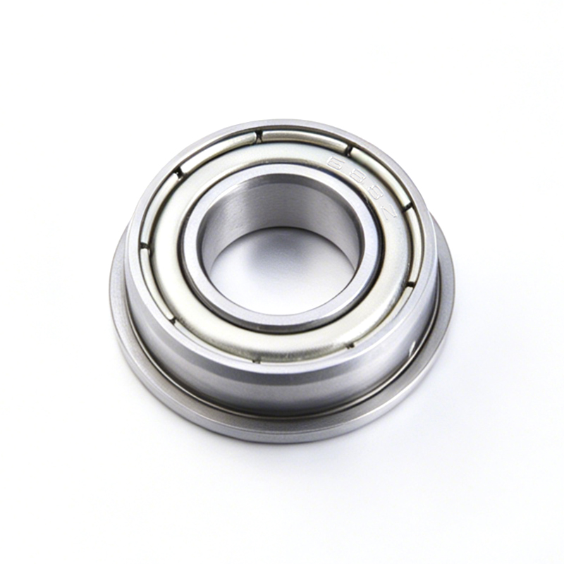
A flanged bearing removes this requirement by extending a thin lip from one end of the outer ring, sized larger than the bore it sits in. The flange rests against the face of the housing rather than a machined internal shoulder, so the housing itself can be a simple straight bore, drilled or reamed in a single pass. This is why flanged bearings appear so consistently in compact electromechanical assemblies, where every added machining step increases cost and every added tolerance increases the chance of a misaligned rotating shaft.

The economic case becomes clearer at scale. A single machined shoulder adds only seconds to a manufacturing cycle on a low volume prototype, but across a production run of tens of thousands of units, that same operation compounds into a meaningful share of total machining time and cost. It also adds a dimension that must be held to tolerance, which increases the chance of a part failing inspection and being scrapped or reworked. A flanged bearing shifts that positioning responsibility onto the bearing itself, a component already manufactured to tight tolerance as a matter of course, rather than asking the housing supplier to hold an additional critical dimension.

Core Components And Their Role In Flanged Bearing Design

How the flange integrates with the rest of the bearing structure without altering the internal mechanics

1

Integral Flange

An extension machined or formed directly into the outer ring, providing the axial stop without any separate hardware or added assembly step.

2

Outer Ring Raceway

Functions the same as on a non-flanged bearing, carrying radial load while the flange handles positioning rather than load transfer.

3

Inner Ring And Bore

Mounts to the shaft exactly as in a standard bearing, since the flange modification is applied only to the outer ring in the great majority of designs.

4

Rolling Elements And Cage

Identical in function to standard bearings, since the flange is a housing interface feature and does not change the internal rolling contact mechanics.

5

Seals Or Shields

Fitted the same way as on non-flanged variants, and the flange face can also help keep contamination from migrating along the shaft into the housing.

6

Mounting Holes On Some Flanges

Larger flanged bearing housings sometimes include bolt holes through the flange itself, allowing direct fastening rather than relying on a press fit alone.

Common Flange Types

Matching flange geometry to the mounting method the assembly requires

Flange Type Description Best Suited For
Round integral flange A continuous circular lip extending from the outer ring, no mounting holes Simple axial location in a through bore, most common in miniature bearings
Slotted flange A flange with cutouts, reducing material and allowing tool clearance during assembly Compact assemblies where full flange contact is not required
Bolted mounting flange A larger flange with through holes for screws, used mainly on bigger bearing units Applications needing a fixed, fastened bearing position rather than a press fit
Thin profile flange A minimal thickness flange designed to add almost no axial length to the assembly Space constrained devices where every fraction of a millimeter matters

Precision Tolerance Classes For Flanged Bearings

How flange geometry itself carries its own tolerance requirement

Flanged bearings are graded using the same ABEC and ISO 492 systems applied to standard bearings for bore, outer diameter, and running accuracy, but the flange adds an additional geometric requirement not present on plain bearings. Flange face squareness, meaning how perpendicular the flange face is to the bearing axis, and flange thickness consistency both affect how evenly the bearing seats against the housing face. A flange that is not square can introduce a small cocking angle into the entire assembly, which shows up as vibration or uneven wear even if the bearing's core dimensional grade is otherwise high.

For this reason, buyers specifying flanged bearings for precision applications should confirm flange squareness tolerance separately from the general ABEC or ISO grade, since not every manufacturer publishes this value by default, and it does not automatically improve simply because a higher core precision grade was selected.

A practical way to request this in a specification is to ask the manufacturer directly for a maximum flange runout value measured relative to the bore axis, rather than assuming a numeric ABEC or ISO grade alone covers the feature. Manufacturers experienced in precision flanged bearing production will have this data available, and a supplier unable to provide it should be treated as a signal to verify flange quality through incoming inspection before committing to a large production order.

Applications Where Flanged Bearings Are The Right Choice

Industries where axial self location outweighs the flange load limitation

Robotics And Automation Small Motors And Actuators Consumer Electronics RC And Hobby Devices Medical Instrument Housings Camera And Optical Mechanisms

In robotics and automation, flanged bearings are used extensively in gearbox stages and joint modules where a straight bore housing keeps the surrounding structure simple while still giving the bearing a reliable, repeatable seated position. In small motors and actuators, flanged bearings mounted directly into a stamped or molded housing eliminate the need for a separate retaining feature, which matters when the housing itself is produced at high volume and any added machining step multiplies across every unit produced.

Consumer electronics and hobby devices, including RC vehicles and small drones, use flanged bearings because the housings are frequently molded plastic, where machining a precise internal shoulder is far more difficult and costly than molding a simple straight bore. In medical instrument housings and camera or optical mechanisms, the flange also serves a secondary purpose by acting as a light barrier against dust and debris migrating along the shaft, complementing whatever seal is fitted to the bearing itself.

Selection Criteria For Engineers

A practical framework for specifying flanged versus non-flanged bearings

Axial load through the flange should stay light. The flange is a locating feature, not a primary thrust bearing. If the application applies meaningful continuous axial load, a dedicated thrust bearing or a properly designed shoulder and retaining ring combination will outperform relying on the flange alone.
Selection Factor Question To Answer Why It Matters
Housing manufacturing method Is the housing machined, molded, or stamped Flanged bearings offer the largest cost benefit in molded or stamped housings
Axial load magnitude How much continuous axial force will the flange actually carry Excessive flange load can deform the flange or loosen the fit over time
Flange thickness available Does the assembly have room for the added axial length of the flange Thin profile flanges exist specifically for space constrained designs
Mounting method Will the bearing be press fit or bolted through the flange Determines whether a plain integral flange or a bolted mounting flange is required
Precision requirement Does the application need controlled flange squareness High precision assemblies should specify this separately from the core ABEC grade

Cost And Manufacturing Tradeoffs

Weighing flange unit price against the machining cost it eliminates

Flanged bearings typically carry a modest unit price premium over an equivalent non-flanged bearing, generally in the range of ten to twenty five percent, reflecting the additional forming or machining step required to produce the flange itself and the added inspection needed to confirm flange squareness. In isolation this premium looks like added cost, but it needs to be compared against what it replaces rather than against the plain bearing price alone.

A machined shoulder in a metal housing typically costs more per unit than the flange premium once tooling wear, cycle time, and the added inspection point are included, and the gap widens further when the housing is a molded plastic part, since a straight through bore is a far simpler mold feature than an internal shoulder with a controlled step height. For high volume production, this comparison usually favors the flanged bearing decisively. For low volume or prototype work, the difference is smaller and either approach can be reasonable depending on existing tooling and design constraints, and a design team should run this comparison against its own actual production volume rather than assuming the outcome without checking real quoted numbers from both manufacturing paths.

Installation Considerations

Practices that preserve the alignment benefit the flange is meant to provide

  • Press against the ring, not the flange. Installation force should be applied to the outer ring face during press fitting, since pressing directly on the flange can bend or crack it, especially on thin profile designs.
  • Confirm bore chamfer. A small chamfer at the housing bore entrance helps the flange seat flush without catching on a sharp edge during installation.
  • Check flange seating across the full face. A flange that seats unevenly against the housing face indicates either a housing squareness problem or bearing damage from installation, and either condition should be corrected before the assembly is put into service.
  • Avoid over torquing bolted flanges. On bolted mounting flange designs, excessive torque can distort the outer ring and introduce preload that was never intended by the bearing design.
  • Verify shaft alignment separately. The flange controls axial position of the outer ring, not shaft alignment, so radial alignment between mating bearings still needs to be checked independently in multi bearing assemblies.

Key Takeaways

Flanged bearings earn their place in precision manufacturing by turning a multi step housing alignment problem into a single straightforward bore, without asking the designer to sacrifice rotational accuracy to get that simplicity.

  • Core benefit: the flange replaces a machined shoulder or retaining ring, reducing housing complexity and manufacturing cost, especially in molded or stamped assemblies.
  • Load limitation: the flange should locate the bearing, not carry primary axial load, and applications with heavy continuous thrust need a dedicated solution instead.
  • Precision detail: flange squareness and thickness consistency deserve their own specification, separate from the bearing's general ABEC or ISO tolerance grade.
  • Installation care: press on the ring rather than the flange, and confirm even seating across the full flange face before the assembly goes into service.
  • Best fit: compact electromechanical assemblies, molded plastic housings, and high volume production where every added machining step carries real cost across the full run.

The overarching principle is that a flanged bearing is a design decision about the housing as much as it is a component decision about the bearing. Chosen for the right reason, in the right load environment, it removes complexity from the surrounding assembly while preserving the same rotational accuracy engineers expect from any properly specified precision bearing. Specifying it correctly from the start, with flange squareness and load limits documented alongside the standard bearing parameters, is what turns a small component decision into a reliable, repeatable manufacturing outcome.

Recent Articles